
Researchers entering slot-die coating for the first time encounter a process that behaves differently from most other thin-film deposition methods. Blade coating and tape casting are intuitive: the applicator contacts the substrate, and the gap more or less determines film thickness. Slot-die coating is pre-metered — the coating weight is determined by pump rate and line speed, not by the mechanical gap between the die and the substrate. This distinction has consequences that are not always obvious, particularly when it comes to understanding the role of slot-die height and how it interacts with line speed.
This article explains the physics behind coating bead stability, why the two most intuitive process levers are imperfect, and why slot-die height (H₀) is the parameter that gives operators genuine freedom to optimize.
The coating bead and why stability matters
In slot-die coating, fluid is transferred from the die to the substrate through a continuous liquid bridge — the coating bead. For this transfer to produce a uniform, defect-free film, the coating bead must reach and maintain a stable steady state, in which the upstream pressure (from the die) and the downstream pressure (toward the substrate) are in equilibrium.
When the bead is in equilibrium, fluid is guided onto the substrate in a repeatable, predictable process. When it deviates from equilibrium, characteristic defects appear:
- Upstream pressure too high: the bead expands, fluid spreads beyond the intended coating area, or dripping occurs.
- Upstream pressure too low: the bead shrinks, entrains air bubbles, or breaks up entirely.
Understanding what drives coating bead pressure is therefore central to controlling the process.
The two intuitive parameters — and their trade-off
The most direct levers for adjusting coating bead pressure are the pump volumetric flow rate (Q) and the substrate line speed (U) (Fig. 1).
Increasing Q forces more fluid into the bead per unit time, raising bead pressure. Increasing U removes fluid from the bead more quickly, lowering bead pressure. This means that when shrinking, air entrainment, or meniscus break defects appear, increasing Q or decreasing U will typically stabilize the bead. When spreading or dripping defects appear, the opposite applies.
These adjustments are effective, but they come with a constraint: because slot-die coating is pre-metered, any change to Q or U also changes the wet-film thickness. In most research contexts, film thickness is a controlled variable — changing it to rescue a stability problem is not ideal. A different mechanism is needed.
Slot-die height as the independent stability lever
Slot-die height (H₀) — sometimes called the coating gap — is the distance between the die face and the substrate surface. It is the third mechanism for influencing coating bead pressure, and it is the one that allows stability to be adjusted without disturbing film thickness.
Raising H₀ stretches the coating bead volume over a larger distance, reducing its internal pressure. Lowering H₀ compresses the bead volume, increasing internal pressure. Because H₀ is independent of Q and U, it can be used to stabilize the coating bead across a wide range of pump rates, line speeds, and target film thicknesses — without altering any of those parameters.
This makes H₀ a powerful optimization parameter, particularly in research settings where film thickness must remain fixed while other aspects of the process (speed, throughput, new formulations) are explored.
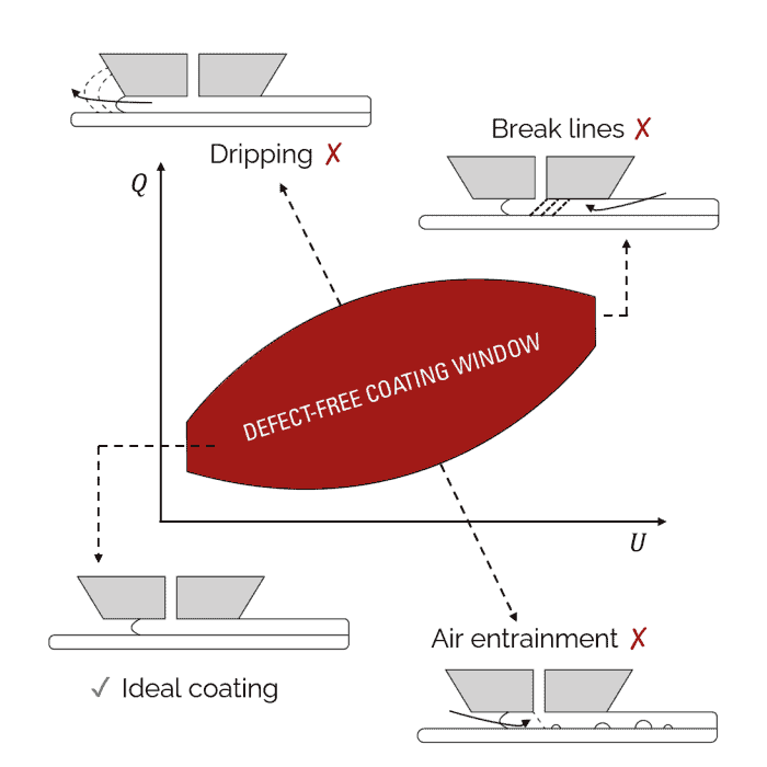
Fig. 1 — Coating process window showing the defect-free zone as a function of pump volumetric flow rate (Q) and substrate line speed (U). Deviations from the stable window result in dripping, line breaks, or air entrainment.
The effect of increasing line speed
When scaling up coating speed — for example, to improve throughput or better approximate industrial production conditions — the relationship between H₀ and U becomes especially important.
For a fixed film thickness, where Q and U are scaled together to maintain coating weight, coating bead pressure tends to decrease as line speed increases. To compensate, H₀ must typically be reduced — the die brought closer to the substrate — to rebuild bead pressure and maintain stability (Fig. 2).
This relationship is well-characterized for proximity coating at moderate line speeds. At very high line speeds, the physics of proximity coating break down, and curtain coating — where the die is held much further from the substrate — becomes the appropriate mode. But for the range of speeds most relevant to laboratory and pilot-scale slot-die research, the inverse relationship between maximum viable H₀ and line speed is a reliable guide.
The practical implication: when optimizing a coating process at one speed and then transitioning to a higher speed, H₀ adjustment should be considered alongside any changes to Q and U. Failing to account for the reduced pressure tolerance at higher speeds is a common source of unexpected defects.

Fig. 2 — For a fixed wet film thickness, the maximum viable slot-die height decreases with increasing coating line speed. This relationship applies to proximity coating at moderate line speeds; at very high line speeds, curtain coating becomes the appropriate mode.
Slot-die height control in FOM equipment
Precise, independent control of H₀ is built into FOM's coater architecture. Both the sheet-based coaters — scalarSC, vectorSC and alphaSC — and the roll-based coaters — nanoRC and arcRC — allow H₀ to be set and adjusted with micrometric precision, independently of coating speed or pump parameters.
This means researchers can use H₀ as a dedicated stability lever without coupling it to other process changes — which is the condition required to use it effectively as an optimization tool rather than just a starting-point setting.
For process development work where speed ranges, formulation rheology, or coating weights are likely to change over the course of a project, the ability to decouple H₀ adjustment from thickness control is practically useful at every stage, from initial bead stability finding through to scale-up parameter transfer.
Read more on the topic

Film uniformity in PEDOT:PSS coatings: why it matters and how to achieve it
Low-viscosity PEDOT:PSS is difficult to coat evenly over large areas. This article explains why film uniformity drives device performance and how the FOM alphaSC achieved below 5% thickness variation on 300 × […]

Enhancing slot-die coating with AI and custom-engineered tools
University of Washington PhD candidate Ethan Schwartz describes his motorized air knife, his use of machine learning to optimize coating parameters, and how he transfers spin-coated perovskite recipes to slot-die coating on […]

Improving the sustainability of products in Europe
The EU is moving toward a circular economy with ecodesign requirements for sustainable products. This article outlines the Circular Economy Action Plan, the proposed ecodesign framework, digital product passports, and public opinion […]

Bibliometric maps of slot-die coating
This article presents an overview of slot-die coating research. A distance-based bibliometric map shows how slot-die coating keywords co-occur in the literature, giving a graphical view of the field.

Printing, coating, metering & the slot-die process
This article introduces the basics of modern printing and coating and explains how wet layer thickness is controlled in different coating processes, including slot-die coating.

The link between slot-die height and line speed
Slot-die coating is a pre-metered process that depends on a stable coating bead. This article explains the relationship between slot-die height and line speed, and how the coating gap can serve as […]

How to choose the right slot-die coater
Choosing a slot-die coater starts with your ink, your substrate, and your goals. This article covers the key questions, from ink viscosity and substrate type to material quantities and plans for scale-up.